LED flashers Vs stock


Manuel

New member
Did you get the relay from the guy selling on ebay

If so his listing only shows 2 pins on the relay plug plus a small earth fly lead

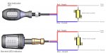
If you have 3 pins plus the earth lead he has sent you in effect a 4 terminal flasher unit, this is not a problem. The 3rd terminal is used for indicator circuits where on the dash board you only have a single warning light to warn the indicators are on, on the bike you have a separate left and right warning light for the indicators so this pin will not be used for our bikes

If as you say you are working now with the original indicators you will be good to go when you fit the led ones

Regards

Gaz
Gaz, very educative posts here, thank you!
I have too bought the LED flashers (front and back) and they are fast. Tried to add the resistors included with the LED flashers (I know, not the preferred way), but that did not help. I found this, I am not sure if a valid option:

Competition Werkes Flasher Relays for Honda/Kawasaki/Yamaha Harness - MPH-HKY - Canada's Motorcycle

Could you please advise if it's a valid option?
Thanks.
 

Gaz2212

New member
Manuel

This may be worth a try as you already have the load resistors, wire the front indicators to the original wiring with no load resistors, then wire in the rear indicators with one load resistor wired across the wiring on the left and the right turn signal so only using 2 load resistors one for left and one for right. Make sure that the load resistor is wired across the indicator wiring and not inline

It maybe that with load resistors on the front and rear circuits that it is creating to high a resistance

Your link advertises that it corrects the flash pattern but with only 2 wires I am not sure how this works, all my experience says that the turn signals will need an earth reference

I have had a quick look on ebay Canada and can't seem to find the device we have got over here, the link below is the relay that we can get and this guy will ship to Canada

INDICATOR FLASHER RELAY YAMAHA R1-R6 FOR LED BULBS | eBay

Hope this helps

Gaz
 

Manuel

New member
Manuel

This may be worth a try as you already have the load resistors, wire the front indicators to the original wiring with no load resistors, then wire in the rear indicators with one load resistor wired across the wiring on the left and the right turn signal so only using 2 load resistors one for left and one for right. Make sure that the load resistor is wired across the indicator wiring and not inline

It maybe that with load resistors on the front and rear circuits that it is creating to high a resistance

Your link advertises that it corrects the flash pattern but with only 2 wires I am not sure how this works, all my experience says that the turn signals will need an earth reference

I have had a quick look on ebay Canada and can't seem to find the device we have got over here, the link below is the relay that we can get and this guy will ship to Canada

INDICATOR FLASHER RELAY YAMAHA R1-R6 FOR LED BULBS | eBay

Hope this helps

Gaz
Thanks Gaz, that will be the project for tonight. I tried only with the 2 resistors in the back, but inline. Did not make any difference.
I noticed that our turn signal bulbs here are rated at 21W and the Euro MT-07 are just 10W (I might be wrong, I was reading that in the respective owners manuals). Would that make any difference when it comes to the relay, if I go that route eventually?
 

afwestpunk

New member
I remember on my old bike that the resistor worked for a short period of time but the Relay solved the issue permanently
 

Gaz2212

New member
Manuel

you need the resistors wired across the wiring not inline, one side of the resistor to the positive wire for the turn signal and the other side of the resistor to the turn signal ground

this picture should help

if you were to get the relay you would not need any resistors at all
 

Attachments

Manuel

New member
Manuel

you need the resistors wired across the wiring not inline, one side of the resistor to the positive wire for the turn signal and the other side of the resistor to the turn signal ground

this picture should help

if you were to get the relay you would not need any resistors at all
Thanks Gaz, I tried the across setup exactly as you mentioned (thanks for the pictures!) and it still did not work. I have already ordered the relay (as you mentioned earlier in this thread, it's obviously the preferred alternative).
Just for kicks, I put 3 resistors in line on the right rear side and it finally worked - not a feasible solution, but at least I found out what was needed for that kind of setup.
 

user1

New member
RE: Post 25 - Wiring Diagram

ahhhh
- a Picture is worth a thousand words... :cool:

Manuel

you need the resistors wired across the wiring not inline, one side of the resistor to the positive wire for the turn signal and the other side of the resistor to the turn signal ground

this picture should help

if you were to get the relay you would not need any resistors at all
 

sir_schmoopy16

New member
I got the Yamaha LED turn signals. The back ones went in fine, but the front ones are a bit of trouble because of the 3 wires. The LED kit only came with 2 connectable wires though and plugging in either of the ground or daytime running light wire results with either no blinking or a dim light. After a while of playing with the wires, I noticed that the first front one doesn't light up anymore. Any reason for that? How do i test to see if the light works still in case i screwed something up?
 
Last edited:


Top